
|
|
|
|
|
|
|

|
|
|
|
MIAMI TECH, INC.
|
|
|
|
|
|
AST Standard Duty
|
|
|
|
|
|
A/C Stand Design Tool
|
|
|
|
|
|
FBC 6th Ed. (2017) - HVHZ & NON-HVHZ
|
|
|
|
|
|
|
|
|
|
|
| |
|
|
|
|
|
|
|
|
|
|
|
|
|
|
|
|
|
|
|
|
|
|
|
|
|
CONTRACTOR & JOB INFORMATION
|
|
Contractor Name:
|
|
Job Name:
|
|
|
Job Address:
|
|
Job City/State:
|
|
, FL
|
|
|
|
|
|
|
|
|
| |
|
|
DETERMINE SITE SPECIFIC DESIGN PRESSURES
|
|
|
|
(STEP 1)
|
Exposure Category:
|
|
|
Lateral Wind Load (psf) =
|
|
|
(STEP 2)
|
Roof Height (ft):
|
|
|
Uplift Wind Load (psf) =
|
|
|
(STEP 3)
|
Windspeed (mph):
|
|
|
|
|
|
|
|
|
|
|
|
|
|
| |
|
|
STAND AND UNIT INFORMATION
|
|
|
|
(STEP 4)
|
|
|
|
|
(STEP 5)
|
|
|
|
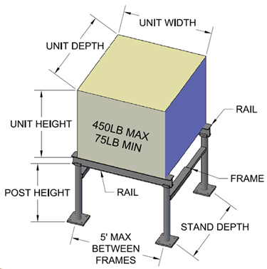
Unit #
|
Width (in)
|
Depth (in)
|
Height (in)
|
|
|
|
|
|
1
|
|
|
|
|
Post Height (in) =
|
|
See Requirements
|
|
2
|
|
|
|
|
Stand Depth (in) =
|
|
|
|
3
|
|
|
|
Number of Frames =
|
|
|
|
4
|
|
|
|
|
Roof Substrate:
|
|
|
|
5
|
|
|
|
|
Part No.
|
|
|
|
|
|
|
|
|
|
|
| |
|
|
DESIGN CHECK SUMMARY
|
|
|
|
Moment
In Post
|
|
|
|
|
|
|
|
Moment
In Frame
|
|
|
|
|
|
|
|
Moment
In Rail
|
|
|
|
|
|
|
|
Axial
Load In Post.
|
|
|
|
|
|
|
|
Frame
Weld (Moment)
|
|
|
|
|
|
|
|
Frame
Weld (Shear)
|
|
|
|
|
|
|
|
Base
Weld (Moment)
|
|
|
|
|
|
|
|
Base
Weld (Shear)
|
|
|
|
|
|
|
|
Channel
Weld (Moment)
|
|
|
|
|
|
|
|
Channel
Weld (Shear)
|
|
|
|
|
|
|
|
Anchor Capacity
|
|
|
|
|
|
|
|
Clip
Capacity
|
|
|
|
|
|
|
|
Moment
CAB Angle
|
|
|
|
|
|
|
|
CAB
Angle Tie-Down
|
|
|
|
|
|
|
|
|
|
|
|
|
|
| |
|
|
|
|
|
This document is not legally binding without
the certification of a Professional Engineer.
|
|
|
|
|
|
|
|
|
|
NOTICE TO ALL CONTRACTORS AND BUILDING OFFICIALS:
|
|
ALL CALCULATION
RESULTS CAN ONLY BE ACHIEVED BY AND USED FOR MIAMI TECH A/C ROOF STANDS
COMPLETE SYSTEM
|
|
OF FRAMES AND I
-BEAMS BEARING THE MTI STAMPED MARKING ON ITS COMPONENTS.
|
|
•
Contractor to determine beam length based on unit width(s) PLUS the required
spacing of units as specified by the euipment manufacturer.
|
|
•
When specified stand depth indicated is greater than the unit to be mounted,
Cross Mounting Angles (MTI part # AS17CAB-xx) are a
|
|
required accessory for installation.
|
|
|
|
|
|
|
•
If no results found using this calculator, please Contact Miami Tech Inc at
(800)-339-2290 for further assistance.
|
|